Thursday, 1 December 2016

Video Meets The Radio Star

Published in Electrosonic's Promag ArchiveClick here to read more.

The days when radio presenters were only heard and not seen are long gone. Radio stations started utilising webcams in studio, to stream live video feeds to websites. A number of radio shows started televising presenters and guests in action. This was the start of a new phenomenon that elevated radio broadcasting to a whole new level: a level that rises higher with every sunrise as new technological innovations see the light.

Digital signage is another key part of today's video technology offering. Video walls are a hot topic currently, and if they are used in concert with other new technologies they produce an extremely functional and impressive outcome. When one combines the above design elements with a GALAXY Video Wall processor and NEC professional displays the result is a breath-taking solution that satisfies even the hungriest technological appetite.

Primedia Broadcasting, a leader in their field with cutting-edge stations such as Talk Radio 702 and 947 Highveld Stereo, decided to do a simple makeover: upgrade their existing studio equipment from analogue to digital, slap on a fresh coat of paint, and replace a chair or two. They kicked off with routine design meetings, but as the team brainstormed through the various options and available solutions, the idea of a simple make-over evolved into a magnificent ‘Complete New Studio’ project with video and digital signage becoming core focus points. Grant Vick, project manager for Primedia explained their motivation: “Initially we only wanted individual screens in each of the new studios in order to display content from social media websites such as Facebook and Twitter, as well as live broadcasting from sport matches and breaking news as it happened. We also wanted to utilise the same screens to display different branding inside the studios at different times instead of the conventional fixed printed branding.”

The Primedia project team then approached Spectrum Visual Networks, a digital media company that has been trading for 12 years. Discussions were initiated by putting the above ideas on the table and Primedia emphasizing the importance of video displays within the new studio design.
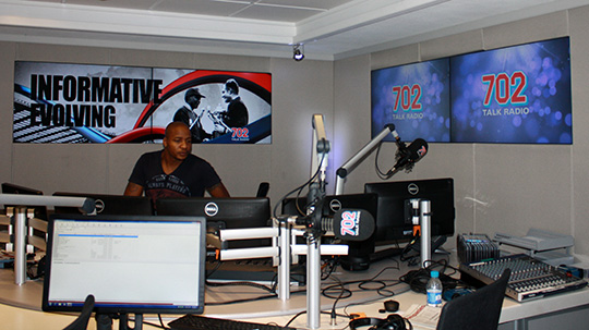
Primedia operates in the ultra-competitive ‘around the-clock’ broadcasting climate, so a successful solution had to be designed with products that offer 24/7 operation and warrantees. This was a piece of cake for Grant Neill, business development manager for Spectrum Visual Networks, who has ample experience in video technology. Grant did his homework and presented a unique digital media solution second to none. This consisted of multiple NEC ultra-narrow-bezel displays, grouped in adjacent clusters, to form a series of 2x2 and 2x1 video walls. The content for these walls was to be driven by a single GALAXY video wall processor per floor. This solution did not only successfully introduce the video element to the studio project, but also opened up other flexible possibilities. These include unlimited branding options during different radio shows and interviews, computer graphics and multiple live television feeds on display at any time.

The Primedia team loved the idea and together with Grant, they paid a visit to the Electrosonic SA showroom for a demonstration and a first-hand experience of the NEC X463UN direct backlit LED displays. The WOW factor was created and they were blown away. The installation, like many others, did not have a smooth execution and presented a hierarchy of challenges. LCD screens inside the studios had to be mounted flush with the acoustic panels and therefore left limited space for mounting hardware. Instead of using equipment pertaining to video wall installations, standard flat brackets had to be used. The latter however, made the panel alignment much more difficult.

Another unforeseen challenge was the noise level of the GALAXY processor which was designed to be inside the call-screen room, sandwiched between the two studios. The call-screen room, which is used for recording phone calls, has to be extremely quiet and even though the GALAXY was configured accordingly, it still didn’t meet the minimum required decibel levels. The only solution was to move the GALAXY processor to a downstairs server room; in theory a rock-solid plan which worked, but was trailed by more complications. The biggest being the distance between the displays and the video wall processor. It was simply too far for aidless HD distribution. One also had to comply with the prescribed – and already over-populated - cable routes into the studios (in studio construction acoustic treatment, ambient noise blanking and magnetic interference are top priorities and therefore don’t allow new cable routes to be made). The distance to be covered was just shy of 90 meters and in order to display full HD signals (1920x1080, 60Hz), Kramer HDMI transmitters and receivers were introduced.

702-web

Kramer’s DigiKat7 shielded twisted pair cable which was specifically designed for this type of application, completed the link. With the GALAXY processor now miles away and all the Kramer distribution equipment in place, the Full HD signals reached the displays problem-free and the images were literally ‘spotless’.

On the software side of the GALAXY we faced two challenges. In the GALAXY Wall Control software layout, the entire wall was displayed as one canvas instead of the multiple smaller walls in the studios. This was easily overcome and the programmer simply had to keep his focus while designing the layouts. Another challenge was the layout selection from individual studios. Each studio has five or six different layout options and because it is driven by a single controller, we had to carefully design layouts to accommodate both studios. This was also not too big an issue and we created a lookup-table of 30 layout combinations in order for each studio to operate independently from the other and still have maximum flexibility.


Graphical user-friendly control is maximised by a single Crestron CP3 processor and three TSW750 in-wall touch panels, one in each studio and the call-screen room. The Crestron system is also used to control the source equipment as well as various lighting zones in multiple areas.
All the elements came together well, composing a stunning final product. "We are very impressed by the final result and the vast functionality offered by the new digital signage system. By using technologies such as these, our studios will always have the edge", said Ryan Till, Chief Operating Officer for Primedia Broadcasting. Grant Neill from Spectrum Visual Networks added: “It was a challenging request, but I am very proud to have been a part of such a unique and successful project”.
At Electrosonic SA we are all smiles. Once again a flagship solution came together by using quality products. It’s the reason why we are in this industry and we strive to meet the future with this same vision. We thank all the stakeholders for giving us this opportunity and for their investment in our arsenal of quality products. The final result speaks for itself.

Wednesday, 12 October 2016

The Bigger Picture


Videowalls are sexy! Any individual who has ever witnessed a single image stretched across multiple display screens will agree. Videowall technologies are growing in popularity and most modern-day retail spaces have at least one videowall to show off to the public.

There are many ways to display a single image across multiple screens but in order to get true videowall functionality, a video processor needs to manage the various inputs and content displayed simultaneously on the larger display area. To AV professionals without deep expertise in videowall technology, the idea of a videowall is a huge mountain of information which most choose to avoid. It seems like too intricate a system to even start understanding. But in reality, videowall basics are pretty straightforward. Essentially there are only two components to a basic videowall: the display hardware and the video source content to be shown. In order to create a videowall, the hardware element requires multiple relevant display screens, with ultra-narrow bezels, installed in a specific array. The most common configuration is a four screen set-up in a ‘2x2’ arrangement. This indicates an extended display area with a width of two screens and a height of two screens. Other basic configurations include 3x3, 4x4, or even bigger arrays. However, the bigger the video wall, the more pixelated the image will appear. These type of arrays are typically used in large scale venues  with greater than normal viewing distances, meaning that the viewer is not very close to the display surface and pixelation detail will not be noticeable.

When designing a basic videowall displaying a single image, it is important to keep the height and the width of the display area in equal proportions to ensure that any image displayed maintains the correct aspect ratio. The ‘aspect ratio’ is an undefined value pertaining to the shape (ratio of width to height) of any display. There are various different aspect ratio standards globally but the most common is 16:9, used for HD video and also the standard in which LCD screens are manufactured. Should a single-image video wall design include more screens in width than in height, or vice versa, it will result in video images appearing out of shape.

In order to display one image across multiple screens, a simple set-up is required. This can be done without the use of a videowall processor if the correct screens are used. Almost all display screens manufactured for videowalls (with ultra-narrow bezels) have a software feature built into the standard menu structure that allows the configurator to set up image sharing or tiling. This feature allocates identities to each screen forming part of the combined set-up as well as its location within the overall configuration. One complete video image is then distributed to each screen either through a ‘daisy chain’ set-up or ‘star’ formation distribution system. Each individual screen will only display the section of the incoming image, based on its identity in the tiling set-up. The user however will experience an impressive giant image displayed across multiple screens – processor free.

Not all videowalls are this basic. More often than not, large display areas are created with custom aspect ratios to service numerous users or viewers simultaneously. In layman’s terms, many operators would view one massive videowall but each individual will only be focusing on a selection relevant to their own contribution. They will be able to view other areas of the wall should an event in another window require their attention. The specific window could then be enlarged across the entire wall, or duplicated in multiple windows for all users to view. In a solution such as this one, it is important to display multiple different sources on the same videowall. For this functionality, a videowall processor is required to manage the incoming signals as well as the extended display area. Custom solutions will require systems to be uniquely pre-configured in order to complement a client’s needs. Many videowall configurations will thus be different from each other.

The videowall processor itself has subcomponents, the most important being the chassis and processing power. Different size frames are chosen to accommodate system requirements. Frame selection is based on processing capacity and slot availability which is to be populated with input and output cards. Many frames can be selected with dual power-supply units and dual hard drives for redundancy in mission critical solutions where unplanned downtime could have catastrophic results. These redundancy components are hot-swappable and can be replaced without interrupting system operation. The next two components are the input and output cards, which are required to capture the source video and supply the correct graphics to the display screens. A range of input cards are available to capture various video formats such as HDMI, 3G-SDI and compressed video streams from TCP/IP systems. Output cards are mostly standard but capable of transmitting both digital and analogue signals to the videowall.

The final component is the wall control software. The videowall software empowers the user to create multiple windows, each displaying an individual source, anywhere and in any size on the entire video wall display area, independent from one another. Videowalls can be used for many custom requirements – from digital signage applications and retail spaces to information centres. The software component is also designed to allow input signal manipulation and it is possible to rotate, flip and custom-crop input signals to display an attractive out-of-the-ordinary display solution intended to catch the eye. Albeit not necessary, external touch-panel control systems are popular to control videowall functionality. Bigger touch panels allow for sufficient real estate to display a graphical layout of the videowall itself and the available input sources and provides a user-friendly dashboard from where the entire videowall layout can be controlled without having to access the configuration software.

A final, but very important part of the videowall installation is the use of a professional manufacturer for the mounting frame. The architecture of videowalls is symmetrical, with multiple square components and careful design and precision installation practice is essential for a pristine appearance. The screens need to be mounted against each other with a micro ventilation space between each screen bezel. The display surface of each screen should be perfectly aligned with the adjacent screens in the wall to provide a flush overall finish. If any of these elements stray from the symphony of exact displays, it will accentuate the imperfection and make the entire videowall appear untidy.


In a nutshell, videowalls are simple. The processor is the palette. The video wall is the canvas. The configurator is the artist.

Monday, 8 August 2016

Touch Me!

click here to read this article in ProSystems Africa News magazine July/August 2016.


These days the words ‘screen’ and ‘touch’ go together like bacon and eggs. It’s nothing new to touch a display screen and expect a relevant response. Consumer grade mobile phones, tablets and most notebooks are all touch-enabled. Interacting with a display has become part of our daily lives.

Many moons ago the idea of touching a display to initiate a command was only known from Hollywood sci-fi. Touch Screen technologies have been experimented with from as early as the late 1960s. However it was only around the turn of the century that we saw touch enabled point of sale systems and interactive information kiosks become more customary in retail spaces. High-end meeting and conference venues utilized state of the art touch overlays over LCD and plasma screens, and back then homes-of-the-future had touch panels with processors controlling their environments. Interactive projection also grew in prevalence, but has never entertained the same levels of attention as touch LCD screens. In the case of interactive projection, ultra-short throw projectors are paired with infra-red or radar devices which cast a separate grid over a projected image. A stylus pen or finger is then used to interact with the grid on a solid surface such as a white board with a low reflective surface.

LCD touch technologies have seen many iterations over the years. Each variation of touch screen architecture focused on the key features - accurate touch and near instant response time - but with an objective of improving a previous result. The biggest challenge in any touch technology is for interaction to be acknowledged by the system and then another challenge is to determine the precise location of the touch on the screen.

The aesthetics of modern day touch overlays such as capacitive and resistive technologies used in smart phones, tablets and kiosks mask very well any visible hint of external technologies. Capacitive Touch screens consist of a conductive coating over a transparent insulator, such as glass. The human body, being an electrical conductor itself, then disturbs the screen’s electrostatic field when touching it. Many variations of capacitive technologies are available, but essentially these function in a similar way. A grid array of sensors is continuously scanned to determine the location of the touch. Resistive Touch screens consist of two layers, each with a fine grid of conductive material placed over each other with a micro cavity in between. The top layer is typically softer, and, when pressed down, makes contact with the bottom layer. A short-circuit registers a resistance in the voltage which will indicate a touch. The X and Y coordinates of the grid determines the location. Not all touch screens are as smooth looking. Alternative technologies have equipment integrated into the bezel of the screen, with protective glass covering the display surface. Because of the integration in the bezel, the latter sits proud from the display surface and could be perceived as a bulky finish.

Surface Acoustic Wave (SAW) and Dispersive Signal Touch (DST) are vastly different technologies but both utilize wave interference by finger touch. SAW systems emit ultrasonic waves over a display from two sides and then measure the same waves from the remaining two sides. An object interfering with these waves will absorb a percentage of the energy and the relevant touch controller then measures the change in amplitude in order to determine the touch location.  DST in turn, measures the bending waves created by a finger touching a display surface from all around the surface area. This is similar to the ripple effect of a water surface when disturbed. Neither of these technologies is very popular because of substantial interference of surface particles such as dust or humidity.

Infra-red (IR) touch systems have IR emitters and sensors around the bezel of the display to form a grid in front of the touch surface. When touched, one or more light paths are broken and based on XY coordinates, a touch, and its location, is registered. Optical Touch systems have LED lights integrated into the bezel, which creates an invisible light layer over the display area. Two cameras from the top corners are monitoring disturbance in the light plane and thus determine touch and location. These technologies do not perform well in very bright environments.

Shadow Sense Touch (SST) is the newest kid on the block. LED lights are integrated into the sides and bottom of a display bezel, with optical sensors in the top corners and top bezel. These sensors measure a shadow created by the interference of a light path. Because of SST architecture being positioned in the bezel, the product, like other optical touch technologies, is also available as a video wall over-frame kit. Individual bezel pieces are mounted around the perimeter displays in a video wall up to 6m in width. These bezels then function collectively to create a touch capable video wall.


SST not only determines a touch and its location, but also identifies the shape of the touch-object used. Software then allows the user to configure a set of parameters in order to accept certain shapes, and ignore others. This feature revolutionized the world of annotations because fingers and pens can be recognized, whilst suit cuffs and hand palms can be dismissed. This in turn reduces headaches, frustration and violence in the workplace.

Sunday, 12 June 2016

OLED: Flattering flat panels

Article published in ProSystems Africa News magazine May/June 2016 edition.
Access on ProSystems Africa News Site

From the late twentieth century onwards we have all witnessed the revolution in TV set technology. Display screens have undergone a noteworthy evolution, in which square box television sets changed to wide rectangular ones, then to flat plasma displays although they weren’t actually flat but only labeled as such in reference to what they used to be. Plasma display panels (PDP) were succeeded by LCD technology which wasn’t much thinner than their predecessor. Only when the compact fluorescent light source got upgraded to LED, did the thickness reduce tremendously. For many years, these LED-lit, LCD panels were the flavour of the month and they increased in either brightness or resolution as new and improved models were released. With each of these technological breakthroughs our minds were blown away and the screens became more appealing every time. Even upgrades within existing technologies were impressive. The next level of display innovation has arrived and recently came to light through many well-known manufacturers at ISE2016. This new technology is known as Organic LED (Light Emitting Diode), more commonly abbreviated to OLED.

Organic LED as a display technology is nothing new. Many film and video production institutions have been experimenting with it for many years. However, it has only recently become available as residential and commercial displays. The OLED display screen is a light emitting technology and therefore doesn’t need a separate light source behind the screen as is required in LCD panels. They can thus be manufactured much thinner than ever before. LCD screens are classed as a transmissive technology, which essentially means that the LCD display merely transmits the light from a separate light source behind the LCD screen. Each pixel in the LCD panel then individually disperses the white light into the three primary RGB (Red, Green and Blue) colours at various intensities in order to display the correct mixture of light required to reproduce the image visible to the viewer. The architecture of these LCD panels requires a screen in front, as well as a light source behind it which adds to the thickness.

In contrast to conventional light sources which emit light by heating a filament until it glows while hot, LEDs are a semi-conducting, solid state light source that require far less energy to produce light. LEDs emit light when electrons are energised through specially treated solid materials that the LEDs are made of. Through this sub-atomic process, low voltage pulses initiate electron movement further away from its proton core and when the energy dissipates, the electron jolts to its original position. During this twitch, alternative energy is released in the form of light. Depending on the length of electron movement, different colours can be created based on the colour spectrum. Organic LEDs are similar to traditional LEDs but the light is produced by organic molecules. In this environment the term ‘organic’ refers to the molecules around the rings of atoms in carbon elements such as wood, plants, petroleum and diamonds. As mentioned above, OLED technology emits its own light and therefore does not require a separate light source. This enables the OLED display products to be extremely thin.

Plasma displays have finally reached the golden years and it has become increasingly difficult to purchase one. PDP is also an emissive technology as the ionized gasses inside the screen emit light. The plasma imaging technology has extremely high thermal emissions albeit very bright and therefore sufficient cooling components are required behind the plasma panel which adds to their thickness. Another downside for PDP is that they consume high levels of energy and the panels are physically very heavy to handle and install. PDP technology has each pixel subdivided into three segments. Each of these sub-pixels is filled with different colour (RGB) phosphor-coated cells which illuminate when energized. The three colours combined at 100% intensity, or variations thereof create the full colour spectrum that forms the image which the viewer can then experience. Plasma display panels have their benefits as well. Because of the panel emitting the light, the black areas were darker, delivering higher contrast between lit and unlit areas. LCD panels have a challenge in this regard as the light source at the back is present even when a pixel is blacked out. This results in black areas appearing dark grey instead of true black. Plasma displays are also capable of delivering very high brightness levels and can be produced in large sizes. However none of these benefits could save its obsolescence.

The imaging technology in OLED displays works by means of a layer of organic semiconductor between two electrodes which emits light in response to electric current. The OLED pixel composition works in a similar pattern to that of a plasma display with each pixel subdivided into three sub-pixels. These are known as RGB OLED displays and each segment contains an organic diode which produces one of the primary RGB colours. Certain manufacturers use WRGB (white, red, green and blue) technology where each pixel is divided into four sub-pixels instead of three. The fourth segment produces white light only, but in order to create white light, one requires a 100% mixture of each of the RGB colours. The architecture to achieve this white segment works somewhat differently to RGB OLED. 

In the case of WRGB OLED, each segment of the pixel is created by compressing different layers of red, green and blue diodes. This sandwich of materials then creates a pixel with four segments delivering white light. A colour filter is applied to the surface area of three of the white segments creating the required RGB light and the fourth segment is left clear for the white light to be visible.

This fourth sub-pixel makes the technology even more energy efficient as it requires only one LED to produce white instead of a combination of the RGB LEDs to deliver the same objective. This results in an energy saving of roughly 60%. Another benefit of having a fourth pure white sub-pixel is the increased brightness when used in conjunction with the remaining RGB LEDs to produce whiter images. OLED displays also offer a much higher contrast as black areas can be completely switched off - as in the case of plasma technology - compared to the light leakage experienced in LCD screens. Additional benefits of OLED are lower thermal emissions and because of the properties of the organic diodes, they can be applied to all kinds of surfaces that make it possible for OLED screens to be lighter, thinner, flexible (bendable and foldable) and generally more durable. OLEDs can also operate in a wider temperature field than older technologies.

OLED products are currently still very expensive but based on the statistics around the costs of developing and producing electronics, pricing can only go one way from here and hopefully, OLED displays will be part of every video project sooner than we can imagine.

Video over IP - the next wave.

Article published in ProSystems Africa News magazine Jan/Feb 2016 edition.

Access article on ProSystems Africa News Site


Traditional video distribution has come a long way since the days of analogue radio frequencies and higher resolution RGBHV signals.

The digital world brought us HD (High Definition) television, but with brand new technical challenges. HDMI (High Definition MultiMedia Interface) was introduced as a HD signal standard with a higher bandwidth requirement for more information transfer between source and sync (display) devices. Because of this, multi-media signals over copper cables are limited by distance. In addition, the HDMI equipment did not accommodate multiple source/multiple display architecture. Another challenge brought about by HDMI is HDCP (High-bandwidth Digital Content Protection). The latter is a control protocol embedded within the HDMI signal. Word on the street has it that Hollywood orchestrated this in an attempt to reduce the criminality around counterfeit copies sold on the black market, which costs content producers in dishonoured royalty obligations. HDCP ensures that both source and sync devices are conforming to a protocol – a digital handshake between licensed devices prohibiting the user from duplicating material.

HDMI soon became the norm in residential set-ups and later on in the professional audio-visual industry where many new technologies facilitated the distribution challenges. In professional video systems, one is more often than not faced with system architecture that requires video signals to reach greater distances than intended for HDMI’s design.Certain systems require video switching between multiple sources and others require multiple displays showing the same content. More advanced systems need a combination of both multiple source and multiple display devices with full routing flexibility. Many different technologies introduced solutions to some of these challenges. 

Balun (Balanced/Unbalanced) systems with transmit and receiver hardware on either side of a STP (shielded twisted pair) cable increased distribution distances but at an expense. More recently, HDMI optical fibre cables function in a similar style with transmit/receiver components integrated at both ends of optical fibre cables with power supplied by the HDMI ports. Fibre cables thus eliminate various components and instead provide a single point of failure with a neater installation appearance. The latest breakthrough in distribution technology is video distribution over IP (Internet Protocol). As more and more audio-visual systems integrate with IT systems, it was only a matter of time before IP networks were introduced to distribute HD multi-media signals. Technologies continue to develop with higher resolutions and current recording, distribution and display devices are capable of 4K UHD (Ultra-High Definition) signals with a resolution of 3840x2160 – four times that of Full HD(1920x1080). Video over IP has changed the architecture limitations of conventional video routing systems. 

Based on customer requirements, conventional systems select a frame to accommodate the configuration required before being populated with components. The negative side to this solution is that the frame size is established by either the number of inputs or outputs to be accommodated. This then results in the other side of the solution having to use the exact same frame even if only a fraction of the real estate is used. IP distribution systems utilise one multi-port switch with transmitters and receivers at both ends of the solution. Each transmitter will convert the HD signal to IP and send it to the IP switch. The receiving end will dictate an IP address where the required source is transmitted from and thus switched to the desired display. This design only requires an IP switch to accommodate the total number of connections (sources and displays) needed in a system. 

The greatest benefit of a video over IP system is that it utilises IT network infrastructure but in order to distribute uncompressed HD or UHD video, network infrastructure must be capable of 10Gb/s bandwidth. This might increase cost but will prepare networks for future IT requirements, assuming that the pace of development around the ‘internet of things’ remains the same. Certain video over IP systems will use video compression and thus require much lower bandwidth capabilities. This makes these systems more appealing because of an attractive bottom line. The question to ask is whether the objective of distributing true HD or UHD video is achieved. Another important factor to keep in mind is the HDCP protocol explained earlier. It might not be required when a local presentation is sent over a network as the content belongs to the presenter. However, the moment one decides to send a HD news broadcast or the latest release blockbuster over a network that is not HDCP enabled, the signal will be rejected by the display device, resulting in a ‘no show’. It is also of high importance to have the initial IT functionality still available on the IT network.


On a 10Gb/s system, each video endpoint is capable of delivering 1Gb/s allocation for internet only. Systems should also be capable of sending USB protocols over the same network and to make it more attractive to the AV professional. Control integration at each endpoint must be capable of delivering Infrared and RS232 protocols. Video over IP technologies are also readily available for the entertainment and staging industry where signal distribution has always been a challenge. System architecture is slightly different with a FOH (Front of House) sender unit – where source components connect – and a back stage distributor switch sending various commands and signals to relevant systems. Both components are linked by a single, two cable connection for redundancy. Some of the supported signals include audio and video as well as control protocols such as Dante and Artnet for lighting control – an important aspect of the live entertainment industry. Equipment is built for rugged on-the-road conditions and the architecture has revolutionised the requirements around live event set-up. In short: the future of video distribution lies with IP networking, with high enough bandwidth to accommodate all the components and technologies in today’s digital world. 

Laser Projectors in the spotlight

Article published in ProSystems Africa News magazine Sep/Oct 2015 edition.
Access article on ProSystems Africa News Site

There is a saucy new item on the projector menu called lamp-less laser projection. Not only is it dripping with solid state lighting goodness but it is also served with a large side order of benefits.

Laser projection, albeit topical, is not just the flavour of the day. With light-source life expectancy of up to 20 000 hours and almost no maintenance, the low cost of ownership is the main appeal. This makes for nearly 10 years of operation on an 8 hour daily, 5-day week basis. The advantages pile up, with higher brightness levels, higher contrast ratios and better colour and brightness uniformity. Also, low thermal emissions result in low noise due to the reduced cooling requirements. Along with a near-instant on/off feature, these projectors really tickle the taste buds and also if that is not enough, lamp-less technology results in an absence of mercury, which makes for a fully recyclable, environmentally friendly product.

Traditionally, projector selection has been based on resolution and brightness, irrespective of the light source. The imaging-technology did play a role but unless it was specified in a system design, it didn’t influence the decision process. Conventional projectors use UHP (Ultra High Performance) and HID (High-Intensity Discharge) lamps. These high-cost lamps operate at extremely high temperatures and offer on average only 2000 to 4000 lamp hours depending on the projection conditions. Such limitations just accentuate the giant leap forward achieved by laser technology. With projector imaging engines being light-source agnostic, laser is an added advantage to current DLP (Digital Light Processing), 3-LCD (Liquid Crystal Display) and LCoS (Liquid Crystal on Silicon) technologies. Laser – along with LED and OLED – is classified as Solid State Lighting (SSL) and utilises a collection of semi-conductors to convert electrical energy into artificial light as opposed to traditional bulbs with energised filaments and gasses (fluorescent and incandescent lamps). The benefits of SSL technology include life longevity and high-quality light intensity sustained over time. It’s also durable, compact and energy efficient. Laser light systems use low intensity beam-expanded laser and can be divided into three sub-technologies namely, RGB laser, laser phosphor and hybrid laser. RGB laser systems have three primary colour laser sources: Red, Green and Blue laser light in distinctive frequencies is delivered directly onto a DMD (Digital Micro-mirror Device) or LCD imaging chip. RGB laser systems produce a very bright image with extra wide colour gamut and brightness uniformity. Unfortunately, they are bulky and expensive, but are ideal for the digital cinema market. 

Laser phosphor systems optimise one blue laser beam onto a coated phosphor surface which excites a variety of primary colours that are processed to create a full colour spectrum image through a 3-LCD or colour-wheel DLP engine. Great colours, with a fairly compact design and high brightness are all positives. Hybrid laser projectors use a combination of laser and LED light to enhance certain primary colours. Contrary to this enhanced colour technology, it results in a narrower colour gamut and struggles to reproduce some colours in the spectrum accurately. Lower brightness is another limitation. Laser projection is a game changer with an extensive list of benefits which cannot be ignored. It brings a new dimension to the projector market and will remain in the limelight for quite some time.

Review: WOW! WHAT A SHOW! MEDIATECH AFRICA 2013

Review published in Promag AV magazine Aug 2013 edition.

Access review on Promag magazine's site

Access review on Electrosonic's Pro AV blog


WOW! WHAT A SHOW! MEDIATECH AFRICA 2013

by Abrie du Plooy - NEC & GALAXY Product Manager
es stand
One thing that cannot be taken away from the audiovisual industry is our flashy side. When we show off, we really show off. And at Mediatech 2013 we remained true to our reputation.
It was as if all the exhibitors secretly decided to go extra 'Wow' this year. A friend of mine paid a visit to see 'what it is we really do'. As she stared in awe at the smoke-filled Coca Cola Dome, ablaze with light beams, laser lights and LED displays, she gasped: "Wow, this is not the type of expo I am used to". That's exactly how it was - it was WOW! The general sense of this year's expo was a markedly bigger presence by the staging & events industry, as well as by the display industry. It was not overpowered by broadcasting folk who seemed to monopolize the attention in previous years. It felt more balanced and all round, every participant played an important role in the overall extravaganza.
z group
The team at Electrosonic SA didn't stand back either and put on its boxing gloves for this bout. The Entertainment Lighting and AV Systems divisions teamed up and the planning started as early as February. Everything was done properly with 3D stand designs and many custom ideas for the big 3 show days in July. The joint effort won Electrosonic SA a Silver Mediatech Stand Award.
Across our stand we accentuated a collection of technologies pertaining to various sectors of the audio-visual industry. Our Lighting division, headed by Bruce Schwartz, filled their section of the stand – as well as every single empty spot other than their own – with the latest lighting innovations, and showed why they are so respected in the industry.
"At Mediatech 2013 we decided to showcase Electrosonic SA as a whole: not as separate lighting and systems divisions. Our stand combined all these aspects as there is a cross-pollination of our products with our clients. So from that point alone we regard Mediatech 2013 as a particularly successful event. We decided to set up a separate area to showcase Martin Professional's Viper range of fixtures in a dedicated space designed to bring out the best in the fixtures optics. We were also privileged to have both Tom Etra from Green Hippo (UK) and Andre Bragard-De Naeyer from ADB (Belgium) on the stand. Because we represent them, Green Hippo also allowed us to set up a captivating 3D Mapping demonstration in the Green Hippo breakaway room. This was definitely a stand-out feature of Mediatech 2013. The quality of Mediatech 2013 was world class and completely on par with European shows like PLASA and Prolight + Sound in Frankfurt. I am sure visitors to the Expo left with lots of valuable information", said Bruce.
bruces
green hippo demo
renier and tom
Opposite the Lighting desks, our AV Systems division, made their mark with Kramer Electronics and Sierra Video products filling an entire 6 metre demonstration area. Jason Johnstone, the Kramer Product Manager had this to say about the show: "Mediatech is always a great way to network with dealers and showcase some of the latest Kramer products. I think one of the biggest benefits is making cross-border contact into Southern Africa. This year we were able to showcase Kramer Electronics' wireless HDMI products which have been in demand lately. We also had our popular SID family on show; a product which won and award for Kramer at InfoComm. In addition to that, Kramer Electronics increased their HDBaseT range of products, as many screen / projector manufacturers are now adding HDBaseT as a standard on their equipment. Sierra Video, a sister company of Kramer Electronics also had space on our shelves; their products included Multiviewers and routers which are aimed at the broadcast market".
IMG 3081
On the display side of things, we demonstrated both our Galaxy Video Wall processors and numerous NEC displays. The baby Galaxy - the X4 - created a very attractive image, spread over a 'smarty box' of displays. The X4 allows users to scale, move and rotate separate quadrants of an image across four individual displays to create a sexy video wall. We utilized 2 x NEC X461S', a 29" dual desktop monitor and a 23" NEC display, in concert to form a very eye-catching display feature, aimed at retail environments. The Galaxy Pro lived up to its name and delivered leading functionality with input and signal management as well as scaling to present a multi-window configuration across four narrow bezel NEC X463UN 46" video wall displays, which in turn had many mouths watering with the crisp Full HD images and high contrast delivered by a full array backlit LED light source. Both products offer 24/7 warranties and built-in redundancy to create an ideal solution for mission critical control rooms and public display requirements. An added Crestron touch panel and processor created a graphic dashboard for the user to orchestrate the required demands.
As far as projectors are concerned, we demonstrated NEC's Full HD PA500U with 5000 ANSI lumens, the PX750U, with its beastlike 7500 ANSI lumens and a smaller UM280Wi ultra-short throw projector with the eBeam add-on to turn any surface into an interactive display, which sparked much interest from representatives from schools and universities.
IMG 3071
andre bruce
As we all know, no projector can fully deliver a quality image without a projection screen at the other end, and Elite Screens, one of the quality products in our arsenal, does just that. Elite Screens accommodate various screen requirements, with a pricing structure to cater for all. The Elite Product Manager, Joel Davies and Linda Swart (Sales & Support) handled the division's area on the stand. "The Elite Screens portion of the Electrosonic SA stand was well attended from far and wide by all sectors of the Mediatech visitor spectrum: Broadcasters, Entertainment & Events companies, and Educational facilities. With our new clients on board, Elite Screens will soon be conquering the wider African markets though visibility and availability. Of the items on display were the line of staging screens, which enjoyed the most attention as well as the various material options across the range of fixed frame and motorised screens," said Linda.
IMG 3155
The rest of the expo floor was covered with demos from many old friends, as well as the odd foe, as competitive industries must have. Mediatech 2013 had much to offer the thousands of industry focused visitors, many of who had travelled across the globe to participate. One of the highlights was 'The Museum', where one could view audiovisual equipment from many moons ago, without which we would not have been where we are today.
IMG 3136
Mediatech 2013 was an overall success and the Electrosonic SA team is very happy with its efforts, and the orders which started rolling in very soon afterwards. Eugene Coetzee, one of the captains of our ship, gave his opinion, "Electrosonic SA's booth at Mediatech 2013 was more than double the size of our booth in 2011. This gave us the opportunity to show off more products and solutions than before. One of the very important design goals of our booth was that it should be easy for visitors to flow through our booth, and we achieved this. Our booth was divided into 3 parts, with an aisle in the middle so we had visitor access from three aisles! I think this really worked well. Our booth was well attended by both existing and prospective clients. It was also a great opportunity to see so many of our clients and integrators in the space of three days. Something that stood out for me in particular when looking at the show as a whole was that exhibitors put in a great effort with the design of their booths. It was on international standard!"
Electrosonic SA would like to use this opportunity to thank each and every one of our stakeholders who contributed and visited our stand. We thank you for your input that resulted in our success, as well as to congratulate the organisers for an event that was well put together. We cannot wait for 2015.

Tutorial: HD BaseT - What you need to know

Tutorial published in Promag AV magazine Sep 2014 edition.

Access tutorial on Promag Magazine's site
Access tutorial on Electrosonic SA Pro AV blog

HDBASET – WHAT YOU NEED TO KNOW

HDBaseT – WHAT YOU NEED TO KNOW
By Abrie du Plooy (Electrosonic SA’s NEC and GALAXY Product Manager)
Recently Kramer Electronics joined forces with Valens, the brains behind HDBaseT. The HDBaseT technology was originally developed by Valens, who formed an HDBaseT alliance (with Samsung Electronics, Sony Pictures Entertainment, and LG Electronics) to contribute to the development of the technology.
Valens is situated just around the corner from Kramer Electronics, and Kramer was hugely involved in the development of the technology, as were some big AV brands. Many AV brands have adapted their product specifications to be HDBaseT compliant.
Electrosonic SA invited Nick Mawer (from Kramer Electronics, UK) and Eli Ofek (from Valens) to tell us more about this amazing technology. What follows is a summary of their expert explanations.
What is HDBaseT?
HDBaseT is the new standard for uncompressed Digital Connectivity. It utilises a 5Play system: a signal that combines 5 elements onto a single Cat5 cable over 100 meters.
The 5 Play Components are:
Video
  • Full HD/3D 7 2K/4K uncompressed video
  • Supports all HDMI 1.4 standards
  • Multi-streaming Capability
  • CEC, EDID, HDCP and more supported
  • Highest video quality with Zero Latency
Audio
  • Digital Audio directly from HDMI chipset
  • All standards are supported, e.g. Dolby Digital, DTS, TrueHD, Dolby Pro Logic, Liz 7.1 & 9.1 and more.
Ethernet
  • Standard 100BaseT Ethernet supported
  • Fall back to standard Ethernet mode
Control
  • Dedicated Control Channel
  • Consumer Electronic Controls (CEC), RS-232, USB and Infrared supported
Power
  • Transmission of up to 100W of DC power
  • Can Power devices such as 60" displays
  • In line with Energy-Star standard
  • No power outlet required
These are the different specification versions:
Spec 1.0
Point to point
  • Integrated support for a single HDMI stream and 100Mb
Ethernet
  • CIR/UART support via continuous oversampling
  • Active/stand-by modes of operation (LPPF1/LPPF2)
Spec 1.1
  • Supports power over HDBaseT (PoH)
Spec 2.0
  • Switch/Network/Control-Point definitions
  • Multi-Stream support
  • USB 2.0, SP-Dif, IR/UART integrated support
  • Flexible A-Symmetric/Partial Link configurations
In short HDBaseT allows you to install a display device 100m from a source device and connect a single cable to send HD signals and power.
Why HDBaseT?
HDBaseT is an approved standard that has been adopted by many players in the industry. It's an elegant, single-cable connection with zero cable clutter. HDBaseT eliminates many multiple cable and cable distance challenges. HDBaseT can be distributed in any AV solution, whether residential, corporate, or hospitality, with a simple HDBaseT network switch - and one does not need separate power. It's especially popular for video distribution in various modes of transport applications. HDBaseT can be used as a single wire system point-to-point, or a multi-connection system. HDBaseT can be daisy chained between devices, with up to 100M between displays.

What is the next step?Firstly, Look for the HDBaseT Logo. Many of the industry's leading brands have already adopted the technology, including Kramer Electronics, Crestron and NEC. Research the supplier's range of technologies and select a product that provides the solution. Read the vendor's collaterals for any disclaimers regarding required functionality. And lastly, test the products in a real-life working situation.
So what are you waiting for?
Electrosonic SA has many products in our arsenal that are already prepared for HDBaseT transmission and decoding. Should you need more information call our office and speak to one of our product managers.